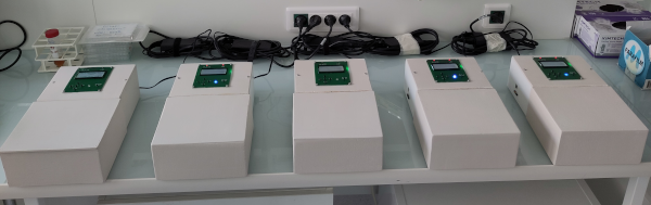
Five MiniRead units at work
Context and Objectives
- The main objective is to be able to perform high-throughput measurement of micro-organism fitness with limited financial investment. The most commonly measured phenotypes to assess fitness components in micro-organisms are related to growth dynamics in different culture media. To monitor growth curves of several hundreds of strains or populations at the same time, we chose to carry out 200uL liquid cultures in 96-well plates.
- For some projects, we needed to run five automatic plate readers at the same time. The temperature of the wells needed to be accurately controled (mostly 30 or 37°C), and to avoid moisture to form under the plate lid, we also wanted the lid to be heated 3 degrees higher than the wells.
- Devices available on the market, that fulfill these requirements, are sophisticated (e.g. work at monochromatic wavelengths) and very expensive, while simple white light is perfectly suitable to measure cell multiplication.
- So we developed a simple DIY plate reader based on measurement of absorbance or scattering of white light. We built five such devices so we can perform close to 500 fitness measurements at the same time.
- The aim of this page is to make the building of a MiniRead rather easy for people having some previous experience in Arduino-based DIY electronics and reasonable soldering skills. On the other hand, it may be difficult without such experience. However, if you still want to make the jump, you can contact me at matthieu.falque@inrae.fr and I’ll do my best to help.
Hardware description
- The device design is based on an inexpensive Arduino Mega board (about 30€), a 8x12 matrix of 3mm white LEDs on the top of hte plate, and a 8x12 matrix of LDR CdS photoresistors under the plate.
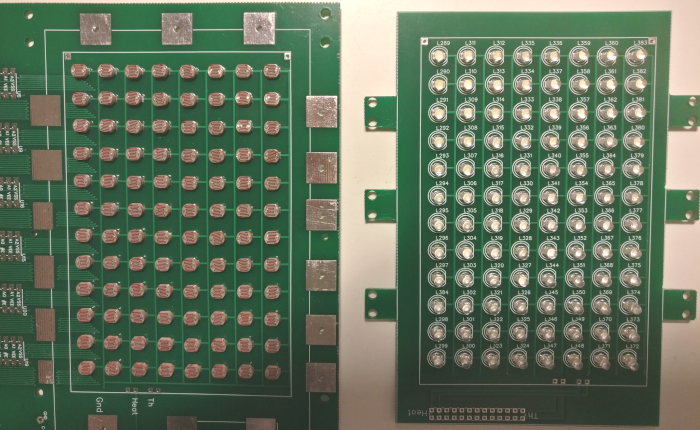
LDR (left) and LED (right) matrices
-
Light intensity is controled (0 to 255) via Pulse Width Modulation outputs of the Arduino board. LEDs are addressed in a matricial way, so each LED is lit once at a time to avoid cross-illumination from well to well. Similarly, each LDR sensor is read once at a time through 12 external 8-channels multiplexers (CD4051) triggered by digital outputs of the Arduino board. This design was chosen to exploit as much as possible the numerous in/out pins of the Arduino Mega, and thus limit external components as much as possible, to make the device inexpensive and simple to build for non-professional electronicians.
-
LEDs and LDRs are fit within 96 holes of two heating plates, one below the culture plate, and the other on top of it. Heating elements are built with resistive metallic wire (5 ohms/m). Temperature feedbacks on the heating plates are obtained from two CTN thermistances, one in each plate in direct contact with the culture plate. The accuracy of temperature control is 0.1°C.
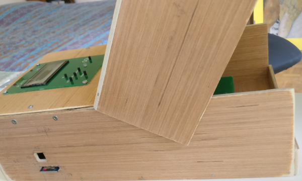
SD card (bottom) and USB port (top)
- Since we wanted the devices to be able to run autonomously without being connected to a computer, the data are written on a standard micro-SD card (FAT-32 formatted) which can be easily pulled out to transfer the data to a computer after the run. The output format is a simple blank-separated text file that can be easily opened by any text editor or spreadsheet software. However, since exploiting the raw reading values requires specific steps of calibration, we have developed a dedicated R package to make analyses easier (see below). A window in the outside cover allows to connect the Arduino board by USB to flash new versions of the firmware using the Arduino IDE.
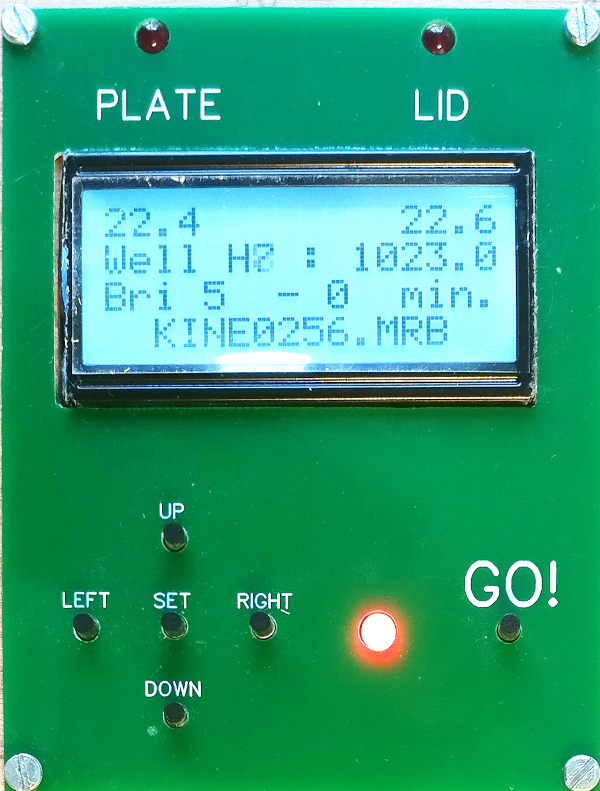
Display and keys
- To make the device autonomous, we have also added a simple user interface based on a 4x16 characters LCD display, 6 keys, and a LEDs. The display shows the plate and lid temperatures in real-time that gives at quick glance an overview of what part of the program the device is currently running. Two additional LEDs also indicate when the heating elements are alimented.
Software description
The MiniRead uses two distinct pieces of software:
-
An Arduino-C++ firmware code drives the multiplexers and LED matrices, reads analog values from the LDR sensors (each reading is the average of 500 acquisitions) via the multiplexers, and controls temperature regulation, LCD display, pushbuttons keys, etc… It can run different acquisition programs allowing for calibration of sensors or automatic growth kinetics monitoring.
This software writes in the micro-SD card text files with raw reading values for all 96 sensors. These values are real numbers between 0 (saturating light intensity on the LDR sensor) to 1023 (saturated darkness). LED light intensity can be adjusted to get the maximum dynamic range for a given model of LEDs, microtiter plate, culture medium and micro-organism (in our hands, a good value for yeast cells in YPD medium is 100, but LED intensity can be set from 1 to 255). However, the raw reading values cannot be compared to each other since the intrinsic characteristics of all LEDs and LDR sensors are very different. Even after carefully selecting LDRs with rather homogeneous measured specs, the remaining variation of response from well to well is such that careful calibration must be carried out. Moreover, calibration is also required to be able to compare cell concentrations from different MiniRead units. We observed that response variation was similar across sensors of the same machine and between different devices. -
An R package to analyze raw output files from the MiniRead devices, with two objectives:
- Analyze calibration data to compute calibration parameters for each sensor of each machine.
This requires first to read plates with different numbers (e.g. 0, 1, .. 16) of layers of neutral optical filter sheet (tracing paper may be just as good). The acquisition program ‘CALIBRATION’ of the firmware was designed for this procedure.
Then the relationship between number of filter layers and raw reading values is analyzed for each of the 96 wells, and modeled using a non-linear method (splines). This allows then to convert any raw reading of any well into a value (arbitrary units which correspond to a number of filter sheet layers) that is linearly correlated to OD, and that can be compared across different wells or even different MiniRead machines.
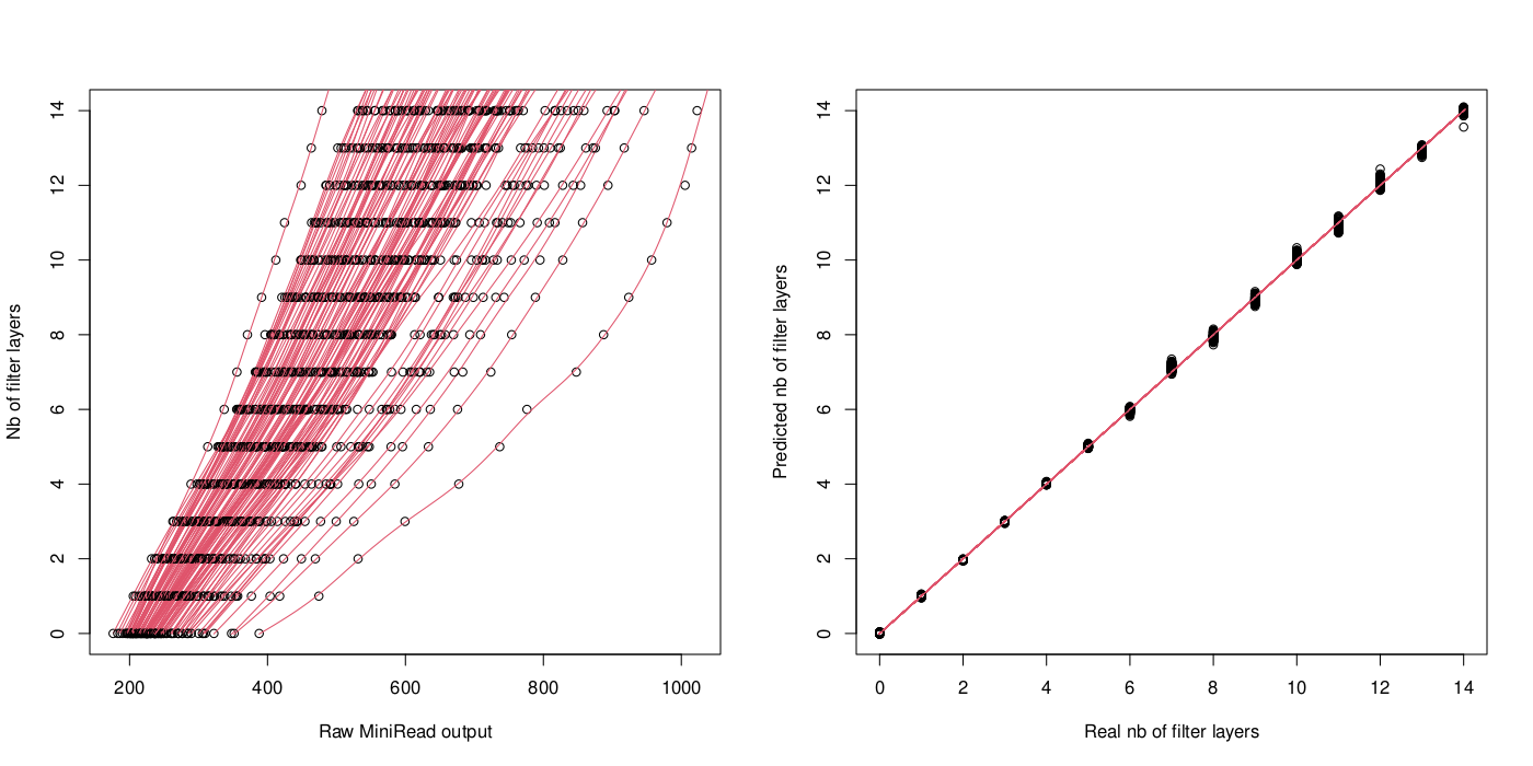
Modeling calibration curves of 96 sensors (left). After correction, all 96 response curves are almost superimposed (right)
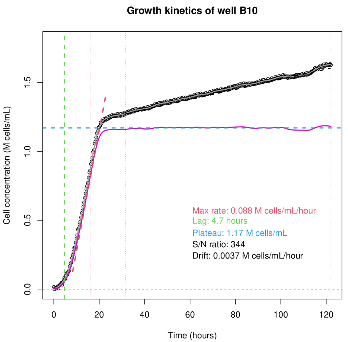
Growth curve analysis (S. cerevisiae in YPD medium)
- Analyze growth curves after applying all corrections based on calibration parameters previously established. This function allows for rapid automatic analysis of 96 growth curves and extracts some characteristic parameters of the growth dynamics. It does not use any mathematical growth model, but tries to identify regions of the curve which correspond to (1) initial lag phase, (2) rapid growth, and (3) ‘plateau’ phase which actually may have some linear slope. Then, the code extracts the following parameters: (1) lag time (before reaching 5% of the plateau value), (2) maximum slope of the curve, corresponding to maximum growth rate during the exponential growth phase, (3) value at the beginning of the plateau, and (4) slope of the plateau. These choices are certainly not appropriate for all applications. They just proved to be useful in some cases for S. cerevisiae fitness measurement. However, different additional custom methods of curve analysis can easily be added based to this function, for instance to implement classical bacterial growth models.
Practical details to build a MiniRead
- The Printed Circuit Board (PCB) files are freely available from [https://forgemia.inra.fr/gqe-base/MiniRead]. We used EasyEda editor to draw the PCB and ordered 5 pieces from JLCPCB, but other export formats (Gerber fabrocation files, SVG and PDF images) are also provided and it should be possible to have the PCB fabricated by any company.
Two distinct PCBs (to be fabricated separately) are necessary to build a MiniRead unit:
- The first PCB contains the main board (bottom right, with arduino, multiplexers, and array of LDRs), the cover plate with the array of LEDs (bottom left), the two heating plates perforated to fit with the LDR and LED arrays (top right and center), and several pieces of board (top left and left) used to build the 96-well culture plate holder.
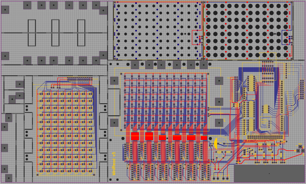
Main PCB with main board, arrays of LEDs and LDR, and pieces of the plate holder
- The five MiniRead units that we have built and that are used in our lab at the moment are based on the V4 version of the PCB. However, a V5 version of the PCB is also available and incorporates some minor improvements:
(1) the Arduino board is shifted to the left to make the USB port closer to the wall of the box,
(2) the 12V power supply connector can be directly soldered on the PCB, and
(3) the connector linking the main board to the display PCB is directly placed on the main board in V5 whereas in V4 one needs to use the small adapter PCB in the bottom of the display cover plate (see below).
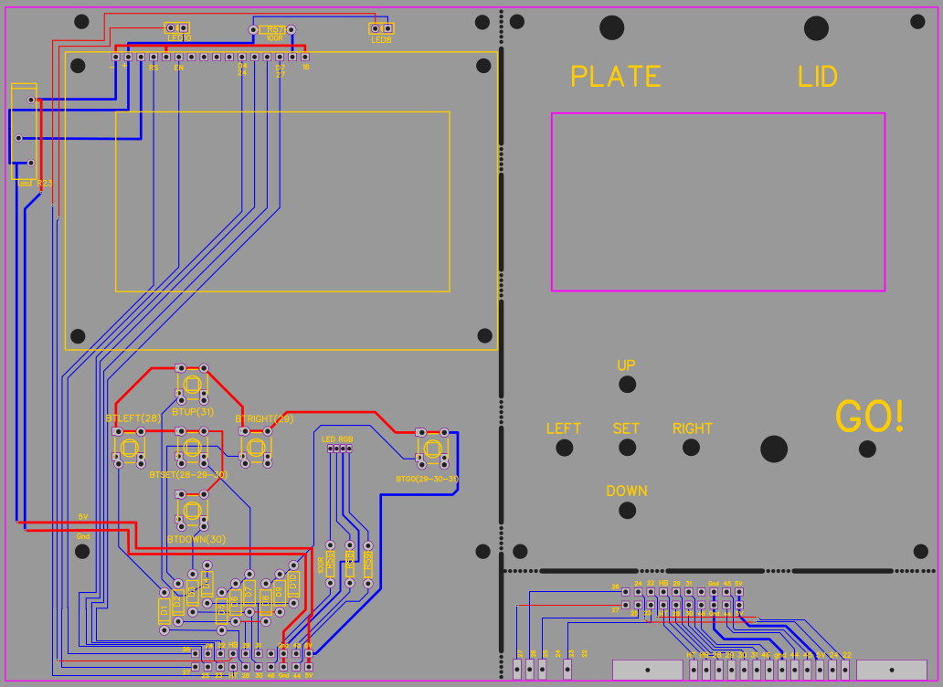
Display and interface PCB + cover plate and adapter board (needed for V4)
-
The second PCB contains the interface board with LCD display, LEDs and keys (pushbuttons), as well as the cover plate with screen-printed indications for users. The bottom right part is not necessary any more in version v5. However, in V4, it must be soldered to the main board to serve as adaptor for the connector to the display PCB.
-
To assemble the MiniRead, it is strongly advised to proceed in the following order:
- Both boards include several parts that must first be separated from each other, and all edges sanded to remove the ‘mouse bites’.
- LDRs are then placed on the main board. We used 5mm LDRs with inter-pin space of 3.5mm. However, the PCB design should also be compatible with 2.54mm inter-pins.
Distribution of LDR resistance under a standard light intensity
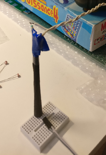
LDR sorting
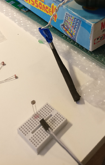
-
An important point is the variation of the characteristics from one LDR to the other. We used GL5516 LDRs which have a resistance of about 5-10 k Ohm @ 10 Lux illumination and O.5 M Ohm in darkness. But even within this reference, the actual characteristics vary quite a lot. To improve the homogeneity of response curves across wells, one can first sort LDRs based on their resistance under a given light intensity (see picture). To do so, we did the sorting by measuring the resistance of each LDR at a fixed distance from a LED powered under a constant current, and protected against exterior light by a cardbox shelter (see picture). In fact LEDs also have variable characteristics, but we did not control that.
-
Once 96 LDRs with similar characteristics are selected, they should be placed on the PCB but not soldered immediately. First, the bottom heating plate PCB (with the largest holes) must be positionned so the LDRs are placed in the holes, and then the LDRs are soldered in the exact right position. The same holds true (even more importantly) later when soldering the 96 LEDs, the top heating plate PCB (with the smallest holes) must be in place when soldering the LEDs.
-
All other compodents of the main board can be soldered now. The PCB includes a number of optional components (2 additional output power transistors, additional CTN and LDR sensors,…) that may be used if needed to implement additional functionalities. We did not use them in the devices we built so far.
-
We do not provide any schematics for the electronics, since most of the job is made by the Arduino board: the external circuitry mainly relies on the 12 chips of 4051 8-to-1 multiplexers that allow to measure 96 LDR outputs with only 12 analog inputs of the Arduino board, and the two power transistors that drive the heating elements with Arduino digital outputs. All other external components are more or less directly connencted to the Arduino input or output pins. Most resistance values are indicated on the PCB or here below. The small decoupling capacitors near the 4051 chips are 100nF.
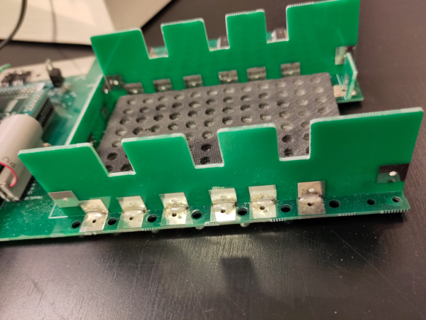
Plate holder assembly
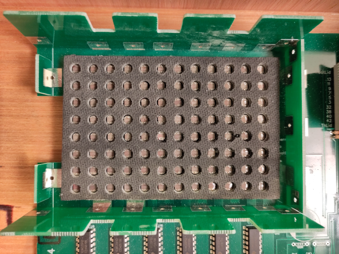
Plate holder with LDRs and bottom heating plate in place
- To make DIY building of the plate holder as simple as possible, all assemblies are done by soldering copper pads so no glue is required, and it’s possible to undo and redo the assembly with a desoldering pump if necessary. The edges of the tenon and niches allowing the heating cover to slide down to the top of the culture plate must be sanded until the cover plate can easily be lifted up and down. This will facilitate placing and removing the culture plate in/from the device.
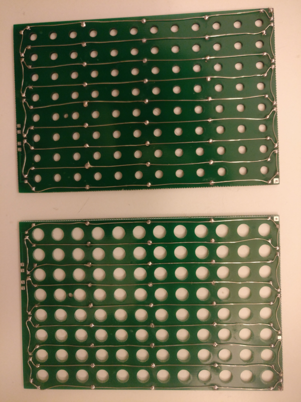
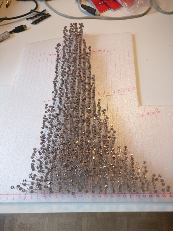
Heating elements soldered on the heating plates
-
To build the two heating plates, we used 6 Ohm/m resistive wire soldered on the small copper pads on the PCB plates. Be careful to avoid thick deposits of soldering to avoid irregularities on the surface in contact of the culture plate. For one plate, the approximative length of resistive wire needed is 160 cm, so the resistance of each heating element is about 10 Ohms. Under 12V power supply, when both heating plates are heating, the overal current drain is thus about 2 to 3 Amps. This is by far the highest source of power consumption of the MinRead, so a 5 Amps 12V external power supply is adequate. It should be a good-quality regulated power supply since voltage variation during the reading can affect the results in spite of the 7805 regulator used to power the Arduino board.
-
Both heating plates are then covered with soft thick rubber cloth. Old mouse pads or thin bathroom carpets can do the job, it just must be soft enough to distribute the heat homogeneously over the surface of the culture plate. The whole surface must be generously covered with glue to ensure a close contact between the cloth and the PCB, and to help making clear-cut holes in the cloth. Then each of the 96 holes must be drilled throughout the cloth while carefully avoiding small pieces of cloth to sit in the optical path through the hole.
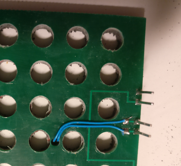
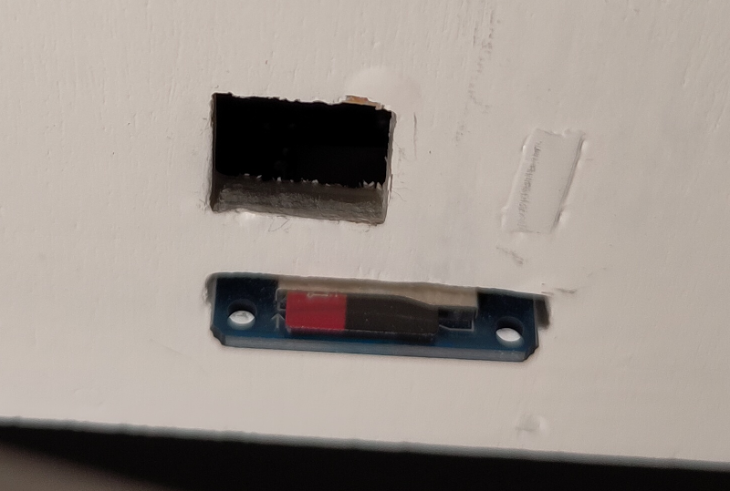
Placing temperature sensor
- Now the temperature sensors (small 15kOhm NTC thermistance) can be placed. Since the heating wire is very regularly distributed on the surface of the plate, each culture well is at the same distance of the neighbouring heating wires, so the temperature is expected to be sufficiently uniform across the plate. So we placed only one NTC temperature sensor at about 1/3 of the length of the plate, and in its middle. The NTC is placed in a small hole through the PCB and the cloth layer (see picture), so it can touch directly the surface of the culture plate. This holds true for the bottom and the top heating plates.
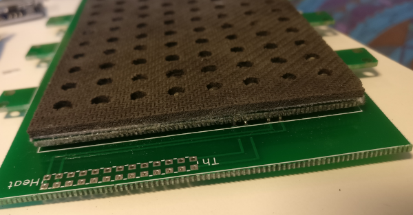
Assembled plate lid
-
Once both heating plates are finished (this is the longest part of the build), they can be put into place: the bottom one has the LDRs placed in the holes, and the top one has the LEDs placed in the holes. Pieces of wire cut from some components can be used to connect the heating plate to the LED or LDR matrix PCB. There are four pins on one side (2 for the heating and 2 for the thermistance, see picture) and two at the opposite corners (one connecting the end of the heating wire, and the other just for mechanical holding).
-
The main board is now almost finished. The card reader module can be soldered in place. In the V5 version of the PCB, there are several possible positions according to the type of box you want to build.
-
The interface board can now be built. Before soldering the LCD display, LEDs, and pushbutton keys, first place the cover plate and fit the LCD, LEDs, and keys in their holes before soldering them. This is particularly important to avoid the keys to get stuck when you press them.
-
Finally, the connectors of the flat cables beween the main board and the plate lid, and between the main board and the interface board can be soldered. Double-check the orientation of the connectors and cables (use the indications printed on the PCB).
-
When all components are in place, please take time to check all connections, and test without the Arduino that there is no short circuit, and that 5V is present at the output of the 7805 regulator.
-
Then you can put the Arduino board in place, flash the firmware, and start with the tests. During the tests, I recommend to use the serial terminal, since the MiniRead program sends out a number of informations that can help to diagnose troubles. It may be useful to do some modifications to the C program to help with first-time use and testing. For instance, the default values must be set into the EEPROM of the Arduino by de-commenting some lines in the source code. Typical value for LED brightness is 100 (0-255).
-
Once the program seems to start normally in the LCD display, you will need to check each LED/LDR pair. First check visually that all LEDs light on and off in turn when scanning a plate (use SINGLE_SCAN program). The probability that you will have to replace some LEDs is not so low… Then place the lid on top of the plate holder without any culture plate, and check all reading values displayed on the LCD display (and in the serial console). All values should be lower than 500 and preferably around 200 to maximize the final dynamic range (dark saturation occurs at 1023). The probability that you will have to replace some LDRs is not so low either.
List of main parts
- Arduino mega 2560 with corresponding connectors to plug it on the main PCB
- 1 regulator 5V 1A L7805
- 2 (optionally 4) BD679 (darlington) transistors to drive the two heating elements plus possible additional outputs (relays, etc…)
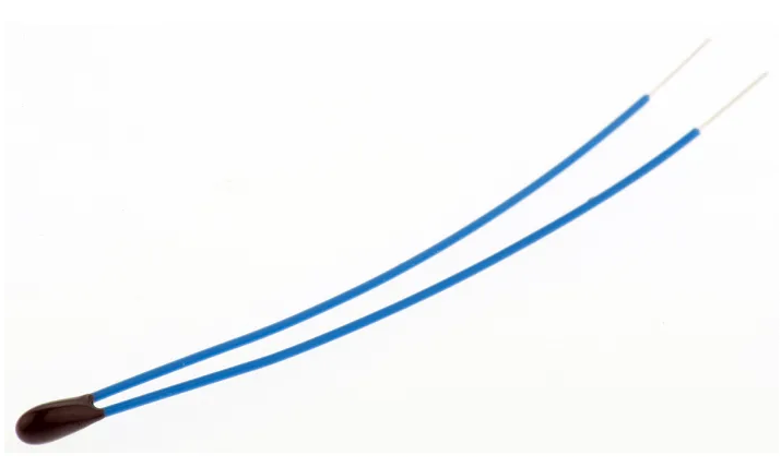
Thermistance
- 2 NTC thermistances 10kOhm 1% (critical). A model with very small head and soft wires is recommended.
- 12 CD4051BE multiplexers
- 96 LEDs 3mm white (may need to be selected for homogeneous characteristics)
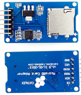
Micro-SD card reader
- 96 LDRs 5mm GL5516 (may need to be selected for homogeneous characteristics)
- 1 LCD display 4 lines x 16 characters (MC41605A6W-FPTLW-V2 or compatible)
- 1 micro SD card reader
- 6 one-way pushbuttons 6 x 6 x 13mm (e.g. TE Connectivity)
- 1 5mm RGB multicolor LED
- 2 female connectors 26 contacts, 2 rows of 2.54mm (e.g. IDC 3M) for flat cable (between main board and lid board)
- 2 female connectors 20 contacts, 2 rows of 2.54mm (e.g. IDC 3M) for flat cable (between main moard and display board)
- flat cable 1.27mm step
Box building
- List of plywood pieces to build the box
| Piece | Size | Thickness |
|---|---|---|
| Bottom | 180 x 320 | 10mm |
| Left-Right | 320 x 181 | 3,6mm |
| Rear-Front | 187 x 181 | 3,6mm |
| TopFix | 187 x 154 | 3,6mm |
| TopCover | 194 x 177 | 3,6mm |
| LeftRightCover | 174 x 181 | 3,6mm |
| FrontCover | 194 x 181 | 3,6mm |
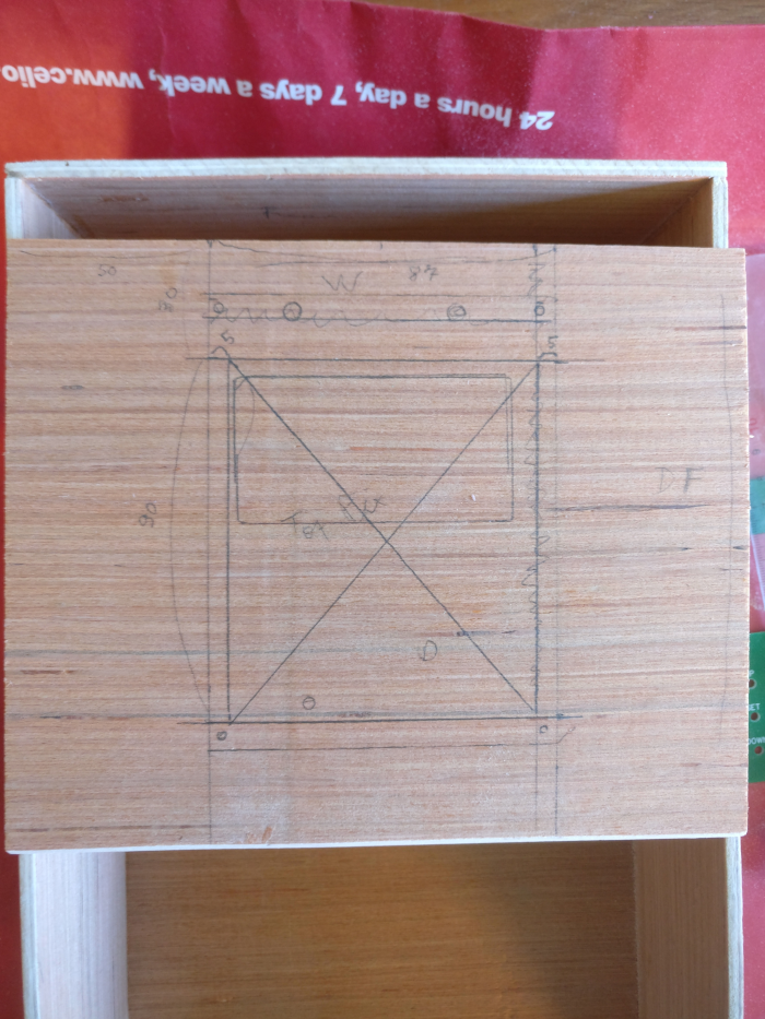
Different sizes may be computed with the help of the following R script:
W <- 180 # bottom plate width (interior)
D <- 320 # bottom plate depth (interior)
T <- 3.6 # thickness of plywood
TB <- 10 # thickness of bottom plate
H <- 80 # height (interior)
FH <- 30 # height (interior) of the front side
DF <- 150 # depth (interior) of the fix part of the top
Bottom <- c(W, D)
Left <- c(D, H+TB)
Right <- Left
Rear <- c(W+2T, H+TB)
Front <- c(W+2T, FH+TB)
TopFix <- c(W+2T, DF+T)
TopCover <- c(W+4T, (D-DF)+2T)
LeftCover <- c((D-DF)+T, H+TB)
RightCover <- LeftCover
FrontCover <- c(W+4T, H+TB)
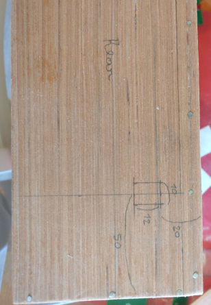
- Different parts of the box
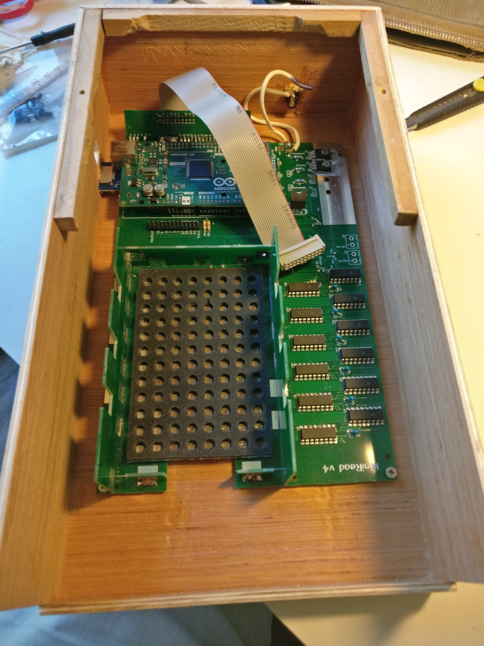
Opened box from top
Interface box plate
Rear with power plug
Left with sd and usb
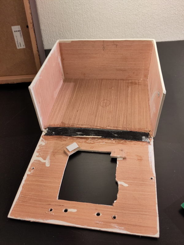
Inside cover
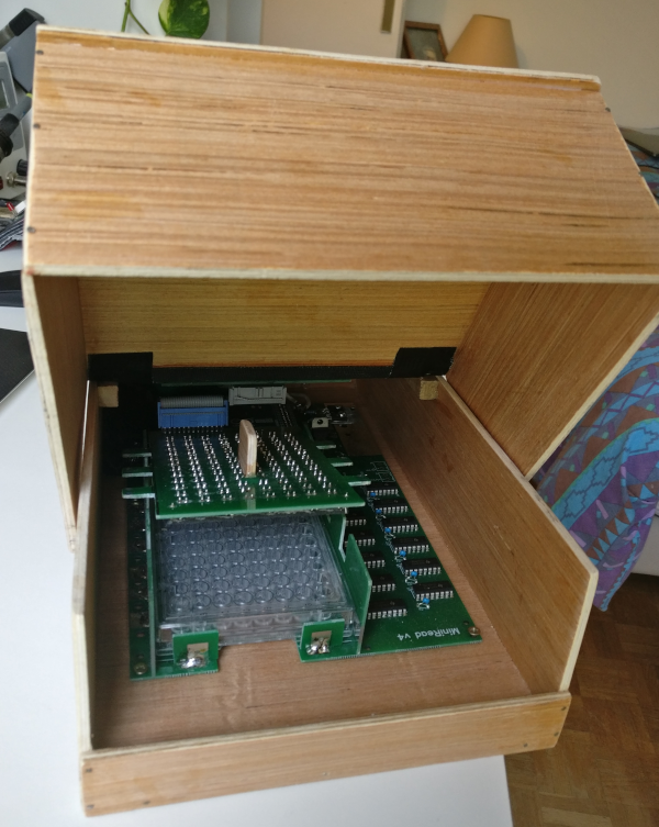
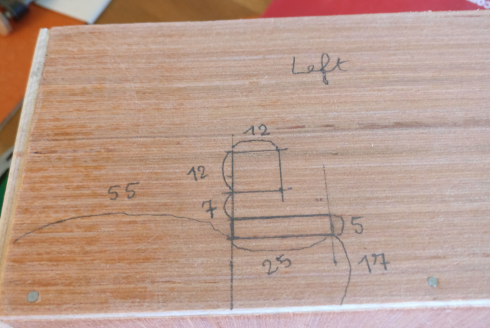
Open box front
Open box left
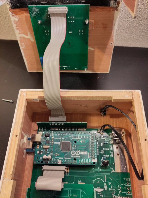
Interface connector in V4